

Julia M Balboni 1, Khawar Siddique 1, Edward K Nomoto 1, Albert P Wong 1, Parham Yashar 1, Patrick S Hill 1, Robert Smith 1, Kristen Perri 1, Brian R Perri 1
Affiliation: 1 DOCS HEALTH Los Angeles, California
Abstract
The ability to navigate the anterior lumbar disc space may improve clinical outcomes and implant longevity. However, no robotic navigation systems are presently authorized by the U.S. Food and Drug Administration to assist with anterior retroperitoneal lumbar interbody surgery. Furthermore, no studies to date have investigated such an application of this technology. This study examines the application of robotic navigation to anterior lumbar total disc replacement surgery to improve retroperitoneal exposure and orientation of the anterior lumbar spine, enhance coronal plane centralization of the implant, optimize surgical trajectory, and mitigate radiologic exposure. Postoperative outcomes of a small cohort of patients undergoing anterior lumbar total disc replacement surgery using robotic navigation were analyzed. The results of the study revealed that a modified use of the aforementioned robot-assisted surgical technology enhances coronal plane centralization and trajectory, all while mitigating radiologic exposure, resulting in more accurate placement of the implant within the intervertebral space at each level.
Keywords:
Accuracy; Anterior retroperitoneal total disc replacement surgery; Coronal plane; Implant; Lumbar spine; Robotic navigation.
Background
The evolution of artificial intelligence technology has altered the paradigm of spine surgery. The recognition that robot-assisted surgical techniques offer benefits absent from conventional approaches has prompted the exploration of broader applications for these methods. 1 In 2004, the SpineAssist, produced by Mazor Robotics Ltd., became the first robotic spinal navigation system to receive United States Food and Drug Administration (FDA) approval. This prompted the introduction of subsequent robots to the field of spine surgery, including the Renaissance Guidance System (Mazor Robotics), the Mazor X (Medtronic), and the ExcelsiusGPS (Globus Medical Inc .).2
The use of multifunctional robotic navigation in spine surgery has allowed for greater precision, reduced approach-related tissue trauma, improved functional outcomes, and decreased radiologic exposure. 3,4,5 In lumbar total disc replacement (LTDR) surgery, accurate midline placement of the prosthetic intervertebral disc is critical to functional success. Asymmetrical implant placement may lead to early post-surgical pain and accelerated wear of the prosthetic components. 6 Despite this, no robotic navigation has been developed or used for anterior retroperitoneal lumbar surgery. This proof-of-concept study examines a small case series of anterior LTDR surgeries to determine whether robotic navigation can enhance the precision of anterior lumbar retroperitoneal midline exposure and trajectory. The technique involves the use of the ExcelsiusGPS robotic navigation system software, robotic arm, and navigation instrumentation, all of which are currently approved for use in posterior lumbar fusion and lateral intervertebral fusion surgery. 5 Study objectives aim to evaluate the possibility of using robotic navigation in anterior retroperitoneal LTDR surgery to 1) improve the orientation of the anterior lumbar spine, 2) enhance coronal plane centralization, 3) optimize surgical trajectory, and 4) mitigate radiologic exposure.
Materials and methods
The study included 36 total patients (1 four-level, 4 three-level, 7 two-level, and 24 single-level LTDRs), consisting of a total of 54 LTDRs with clinical indications for total disc replacement, which were identified as appropriate candidates for anterior retroperitoneal surgery. Of the 54 total LTDRs, 32 were not navigated, while the remaining 23 LTDRs were navigated. This study proceeded under local institutional review board approval and with informed consent from all human subjects. The implant utilized in the single and multilevel LTDRs was the Centinel Spine ProDisc-Lumbar (ProDisc-L). The chosen robotic navigation system was the Globus ExcelsiusGPS, which currently contains software to assist surgeons in posterior lumbar pedicle screw placement and lateral intervertebral disc preparation, trialling, and interbody fusion surgery.
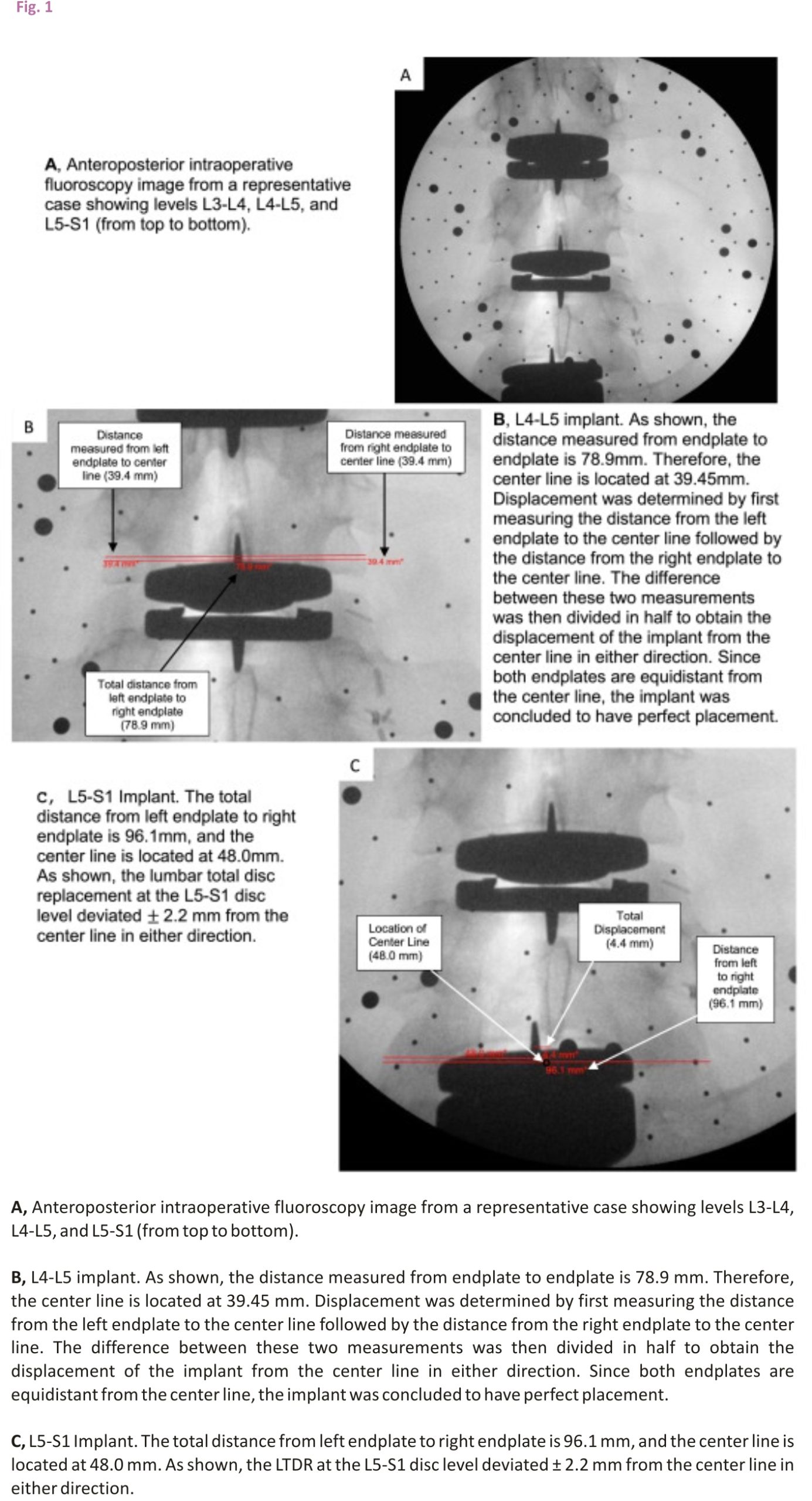
Anteroposterior (AP) radiographs optimize the anatomical detail of the vertebral body. This study utilized postoperative AP radiographs and intraoperative AP C-arm fluoroscopy images to assess the deviation of the implant from exact midline placement in both the coronal and midsagittal planes. For all measurements obtained in this study, a true anteroposterior anatomical image served as a standard reference. The true AP image was obtained with respect to the vertebral disc and bony anatomy. The plane created by the angle of the implant keel was not taken into account when determining the standard of reference.
To determine the degree of accuracy associated with each LTDR, an independent evaluator measured the displacement of the implant off the centre line. The centre line was defined as half the distance from the left vertebral endplate to the right vertebral endplate. The distance from the left endplate to the centre line was then compared to the distance measured from the right endplate to the centre line (Figure 1). The difference between these two values was then divided in half to obtain the displacement of the implant from the centre line in either direction. Measurements were obtained using the cephalad vertebral level for all LTDRs. Postoperative computerized tomography (CT) scans were utilized in 5 patients to successfully validate the x-ray measurement methodology employed in this study.
The selection of vertebral endplates as margins was first utilized in a 2005 study investigating the safety and efficacy of LTDR surgery 7 and then again by researchers in a 2012 study evaluating the relationship between LTDR surgical accuracy and clinical outcomes. 8 Both studies identified endplate boundaries as a reliable metric when measuring digital radiographic images in the coronal and midsagittal planes.
To evaluate whether robotic navigation facilitates more accurate placement of the LTDR, the average displacement across all levels in the navigated group was compared to the average displacement across all levels in the non-navigated group. An independent, two-sample t-test was performed to evaluate whether a statistically significant difference exists between the means of the two groups. In addition, the average radiologic exposure of patients in the non-navigated group was compared to that of patients in the navigated group for one-level, two-level, and three-level LTDRs. Between-group comparison was not conducted for four-level LTDRs, as only one patient in the study underwent this type of surgery.
Surgical procedure and technique
To modify the navigation system software, the surgeon began by placing posterior pedicle screws across the disc level to receive the total disc replacement. The screws were never intended to be placed, but rather functioned to allow for intervertebral navigation by providing the software with anatomical location data. Once in place, the software displayed the location of the pedicle screws on previously obtained and uploaded preoperative CT or intraoperative anteroposterior and lateral fluoroscopy images. These images were displayed on the navigation system monitor for view by the surgeon.
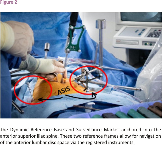
Two reference frames were then anchored into the anterior superior iliac spine (ASIS). The Dynamic Reference Base (DRB), which contains four reflective spheres, was first placed into the left ASIS, followed by the placement of the single sphere Surveillance Marker into the contralateral ASIS (Figure 2). The DRB can be thought of as the origin of the coordinate system about which the navigation system operates. Together, the DRB and surveillance marker form the DRB-surveillance marker complex and function to detect movement that may occur between the two reference frames during the operation. If movement is detected, the navigation system will alert the surgeon and recommended a landmark navigational accuracy check be performed to avoid the robotic or navigational error.
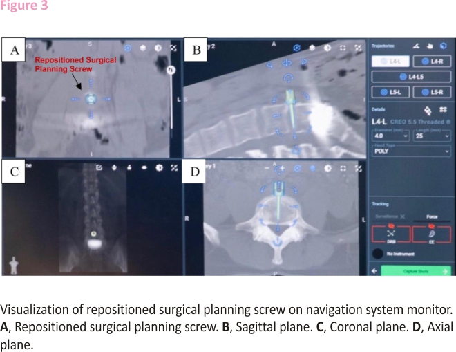
After the software completes registration of the disc space, one of the surgical planning screws is removed and repositioned on the navigation system monitor perfectly midline and perpendicular to the spine in the anterior interbody space. The precise location of the repositioned screw can then be visualized on the navigation system monitor, which will leverage the algorithm within its software to merge the preoperative CT scan and intraoperative fluoroscopy images to provide a final image that can be viewed on axial, sagittal, and coronal plane imaging (Figure 3). Instrumentation used for navigation is registered with the software once it is brought into the sterile field and placed in the line of sight of the navigation system camera. The navigated instruments that can then be used by the surgeon include the Landmark Probe, also known as the Verification Probe, lateral cobbs (20mm, 10mm, 20mm 7° up, 10mm 7° up), lateral ring curettes (10mm, 10mm 7° up), lateral cup curettes (serrated, serrated 15° up, serrated 90° down), lateral double rasp, lateral scraper (5mm, 7mm, 9mm), slide hammer, and lateral disc prep graphic case. This study identified the Landmark Probe, lateral cobbs, and lateral cup curettes to be most useful in anterior retroperitoneal LTDR surgery.
All navigated LTDRs were compared to a non-navigated cohort. The procedure for non-navigated and navigated LTDRs differed only with respect to implant insertion. Without the use of the robotic navigation system, non-navigated implants were placed according to anatomic and fluoroscopic landmarks. It is important to note that anatomic landmarks were sometimes difficult to obtain when surgical exposure was restricted due to scarring, osteophyte formation, or vascular adhesions (especially in revision anterior retroperitoneal exposure or anterior disc herniations). Consequently, the access surgeon was occasionally not able to provide an exposure that was perfectly centred over the midline anterior disc space. For example, retroperitoneal vascular adhesions in one patient resulted in the exposure being off-centre to the patient’s left. Consequently, the retractors and disc access were also off-centre, making the orientation of the anterior disc space and implant insertion difficult. After the implant was placed in this non-navigated patient, the patient required reoperation for posterior decompression of the lateral recess and neural foramen. While the left-side decompression was performed without complication, decompression of the right side was challenging due to limited access to that side of the spine.
Furthermore, retractors are not perfectly radiolucent and can interfere with intraoperative imaging. To produce a lateral image, radiation waves penetrate only the width of the retractor blade, allowing for minimal interference. In contrast, to produce an AP image, radiation waves must propagate through the entire length of the retractor. The increased distance through which the waves must travel in an AP image creates significantly more interference compared to that of a lateral image. As a result, retractor interference inhibited fluoroscopic guidance in some non-navigated LTDRs.
Navigated surgical procedure and technique using L4-5 LTDR example
The patient’s preoperative CT scan was first uploaded onto the navigation system software, and screws were planned on the navigation system monitor for an L4-L5 lateral intervertebral fusion, with two pedicle screws planned at L4 and two pedicle screws planned at L5. Once the software completed its registration of the disc space, one of the surgical planning screws was repositioned within the L4-L5 disc space, exactly midline and perpendicular to the axis of the spine. The Quattro Spike was then inserted into the patient’s left ASIS. The DRB was then placed into the Quattro Spike, with the reflective spheres located on the DRB facing in the direction of the navigation system’s camera. Next, the Surveillance Marker was inserted into the patient’s right ASIS, acting as a second reference marker. The navigation system’s camera then captured these two reference markers, registering the system for navigation.
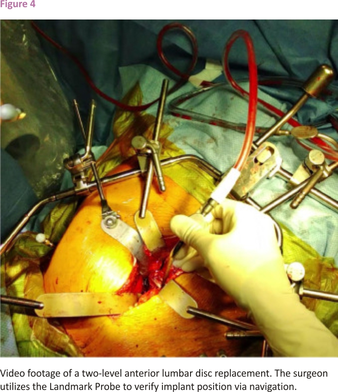
Next, fluoroscopy images were obtained and verified with the Landmark Probe. The fluoroscopy was used in a biplanar mode to plan accurate exposure of the intervertebral disc space. This was accomplished by allowing the software to capture the position of the spine in space via passive marker arrays on both the Fluoroscopy Registration Fixture and DRB-Surveillance Marker complex. The fluoroscopy images were then assigned manually on the robotic system to all vertebral levels of interest. For each vertebra, a centroid was placed on the overlapping anteroposterior and lateral fluoroscopy image and the system was instructed to merge the CT scan with the intraoperative fluoroscopy images. To verify system registration, the preoperative CT slices were manually compared to the intraoperative fluoroscopy images to ensure that no anatomical shifts occurred. Using the Landmark Probe, navigation was employed to identify the midline of the disc space, which was then confirmed with x-ray imaging following exposure of the anterior spinal column and disc space. The video in figure 4 shows the surgeon utilizing navigation via the Landmark Probe to verify implant position. Disc space preparation was then performed via a radical anterior lumbar discectomy, endplate curetting to the subchondral bone, resection of the posterior longitudinal ligament, and microdiscectomy when necessary.
After decompression of the bilateral neural foramen, lateral recess, and central canal, the disc space was trialled to determine appropriate LTDR disc height, length, width, and lordotic angulation. Once the ideal trial was identified, navigation was used to assist with the insertion of the implant. The registered Landmark Probe, aligned with the shaft of the chisel, verified the locational accuracy of the intended orthogonal keel cuts, which were displayed on the navigation system monitor. The chisel was then advanced to create the keel cuts at the chosen angle of insertion and point of coronal centralization within the intervertebral disc space. Final anteroposterior and lateral fluoroscopy images confirmed the positioning of the implant.
Results
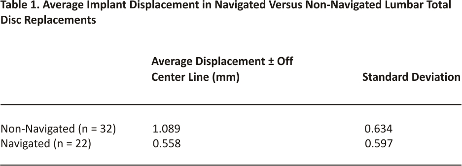
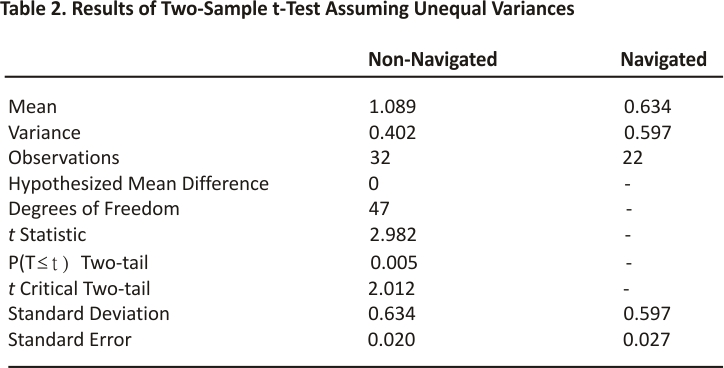
The implants placed with the assistance of the robotic navigation system exhibited, on average, less displacement from the centre line compared to non-navigated trials. The average displacement from the centre line across all levels in the non-navigated group was ± 1.09 millimetres (mm). The average displacement from the centre line across all levels in the navigated group was ±0.56 mm. The results obtained by an independent two-sample t-test assuming unequal variances revealed that there is a statistically significant difference between the means of these two groups. With an alpha level of 0.05 and a two-tailed test, the mean displacement from the centre line for navigated LTDRs was significantly less than the mean of non-navigated LTDRs, t(47) = 2.012, p=0.005. All navigated implants exhibited a displacement of ±1.78 mm or less from the centre line, with the exception of one L5-S1 level shown in Figure 1. The implant at this L5-S1 level exhibited a displacement of ±2.2 mm in either direction, which was attributed to poor vascular exposure.
A planned revision microdiscectomy was necessary for multiple patients of this cohort prior to the final placement of the LTDR. This was completed anteriorly with the assistance of navigation via the use of the registered instruments, specifically the Landmark Probe and lateral cup curette, to ensure thorough removal of disc material and surrounding scar tissue.
As previous studies have demonstrated, intraoperative navigation affords the surgeon better visualization compared to conventional methods. 9 In this study, the registered instruments were able to be used to navigate the lateral recess, spinal canal, and neural foramen. While the efficacy of decompression by robotic assessment was not part of the collected postoperative data, assistance with decompression became an apparent and notable advantage of this technology over the course of the study. By allowing for navigation of areas often difficult to visualize, such as the lateral recess and neural foramen, the surgeon was able to confirm adequate decompression lateral to the pedicle of the caudal vertebral level in these cases. This enhanced surgical confidence that the exiting nerve root and dorsal root ganglion were effectively decompressed.
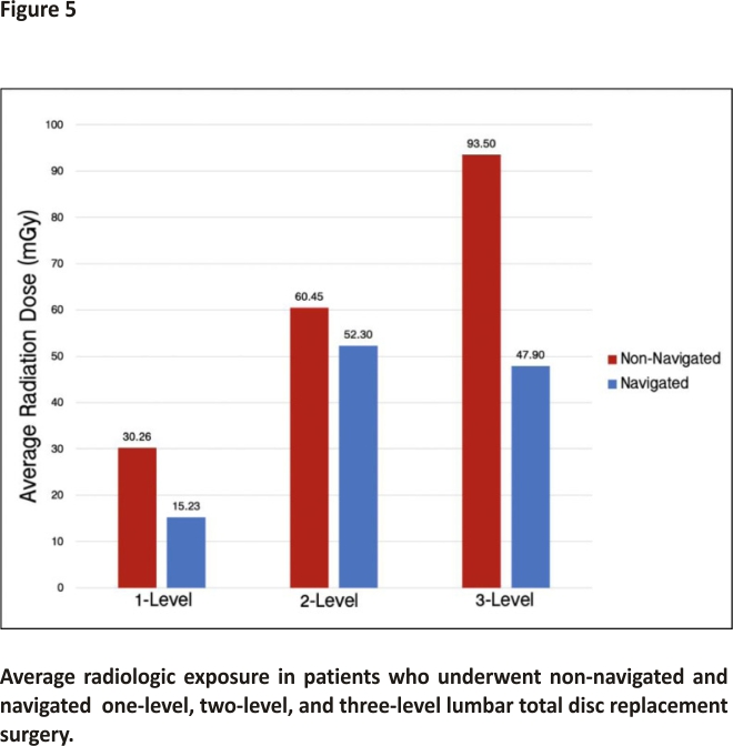
Patients in the navigated group were exposed to less radiation, on average, compared to patients in the non-navigated group (Figure 5). The average dose of radiation received by patients who underwent a one-level LTDR was 30.26 milligrays (mGy) in the non-navigated group compared to 15.23 mGy in the navigated group. For patients who underwent a two-level LTDR, the average dose was 60.45 mGy in the non-navigated group compared to 52.30 mGy in the navigated group. Lastly, for patients who underwent a three-level LTDR, the average dose of radiation was 93.50 mGy in the non-navigated group and 47.90 mGy in the navigated group.
Discussion
Accurate placement of the LTDR within the intervertebral space at each level was able to be accomplished using this novel robot-assisted surgical technique. Small miscalibrations were encountered during the first two navigated trials due to slight inaccuracies with the navigated instruments, specifically the lateral curettes and Landmark Probe. Failure to reregister the spine after intervertebral disc work and trial was determined to be the cause of these inaccuracies as spatial changes, relative to the presurgical CT scan, inevitably follow discectomy and disc space remobilization.
Disc space preparation inherently alters the cranial-caudal vertebral relationship due to changes in intervertebral disc height and sagittal alignment that occur when the trial is positioned within the disc space. 10 Given that complete discectomy, anterior and posterior longitudinal ligament release, and remobilization, especially in severe spondylotic disc segments with disc height collapse, significantly alter the relationship of the surrounding vertebrae and intervertebral disc, 11 reregistration should be performed before keel cuts are made to ensure correct sagittal alignment. This re-registration must occur with the final disc space trial in place and should follow the discectomy, restoration of disc height, and disc segment remobilization. Reregistration can be performed as many times as necessary to allow for accurate navigation during the disc space remobilization or neural decompression portions of the surgery. Reregistration allows the navigation system to accurately reference changes in spatial orientation within the caudal and cranial vertebra and intervertebral disc space.
The surgeon should be wary of potential sources of interference. The navigation system camera identifies the reflective spheres located on the reference frames. If the spheres are incorrectly loaded, not fully seated, or contaminated with blood or fluid from irrigation, the accuracy of the navigational instruments can be compromised. Navigation is not possible until the cause of interference has been corrected.
The learning curve of this applied technology is relatively rapid. In this study, it took the lead surgeon five cases, of which the initial case resulted in approximately 30 additional minutes, to become proficient in the navigated technique and technological set-up. In each subsequent case, operating room (OR) time progressively decreased. After the fifth case, total OR time increased by only approximately ten minutes, attributed to the insertion of the DRB-Surveillance Marker Complex. A small, 5 mm incision is made overlying the left ASIS to allow for insertion of the DRB. A separate 5 mm incision is made on the contralateral side to allow for insertion of the Surveillance Marker reference frame. Once the implant is placed, the two reference frames are withdrawn from the patient and a Steri-Strip is used to close the two 5 mm incisions.
As with most studies, the design of the current study is subject to limitations. Due to the lumbar lordosis, the angles of each disc space in the sagittal plane vary.12 Thus, the anteroposterior postoperative x-ray images obtained in this study lack the perfect tangential that is obtained intraoperatively. Additionally, to increase the statistical power of these conclusions, additional studies are needed to increase the size of the investigative sample.
In consideration of the potential adverse effects of radiation exposure, postoperative CT images were not obtained for all patients. 13 Instead, CT imaging was utilized in five patients prior to the solidification of this study design (all of whom required imaging to evaluate postoperative radicular symptoms) to validate our measurement technique. Comparison of CT, X-ray, and intraoperative fluoroscopy images confirmed the accuracy of the measurement methodology utilized in this study.
It remains undetermined exactly how far off midline an implant must be placed before complications arise. A 2005 study evaluated the accuracy of implant placement according to the total distance, in millimetres, of the implant from exact central placement. The results revealed that deviation ≥3mm from exact midline placement is associated with pain, abnormal motion, and accelerated wear of the prosthetic disc. 7 The measurement methodology utilized in the present study differed from that of the previous study in that it evaluated implant displacement in either direction from the midline. This difference is important when considering study results. The authors of the present study believe that the clinically significant value of 3 mm identified in the 2005 study is likely equivalent to a displacement of ± 1.5 mm in the present study. While future studies are needed to identify how deviation values within 3 mm of the midline impact clinical outcomes, a known correlation between surgical accuracy and LTDR efficacy exists, 8 and image guidance has been proven to significantly improve lumbar arthroplasty placement. 4
Furthermore, it is important to note that one patient in this study developed neurological deficits postoperatively, which were determined to be the result of a malpositioned implant (Figure 6). This patient was in the non-navigated group and required revision surgery. The repositioning of this implant one day after the index surgery resolved the patient’s symptoms. Intraoperative fluoroscopy in this patient was with poor resolution on both anteroposterior and lateral views due to large body habitus. Additionally, vascular exposure difficulties were encountered due to inflammation, which resulted from an anterior L5-S1 disc herniation.
Given that two-year follow-ups are widely considered to be the gold standard when evaluating surgical success, it is likely that longer-term follow-ups are needed to evaluate how accurate coronal plane LTDR placement impacts implant longevity and range of motion over time.
Clinical applications
Surgical exposure can be challenging due to irregular vascular anatomy, osteophyte formation, and inflammation caused by prior spinal surgeries and procedures.15 Primary, and especially revision, lumbar spine surgery can be further complicated as a result of scarring and adhesions within prevertebral soft tissues. 16 In cases accompanied by such complications, mobilization of the vasculature to allow for thorough anterior exposure of the lumbar disc space is associated with the risk of major vascular bleeding. These challenges can hinder exposure of the anterior disc space and make it difficult for the surgeon to determine the midline of the disc space. The application of retroperitoneal navigation to improve neural decompression and accurate LTDR implantation is especially useful given that imperfect spine access is common.
While radiographic indicators can be used to assist with accurate LTDR implantation in the absence of navigation, the thickness of the keel on a true anteroposterior image appears smaller when the implant is placed tangentially than when it is oblique. Additionally, rotation of the spine may compromise the utility of anatomical landmarks (Figure 7). Although additional x-ray images can serve as a compensatory recourse, the alternative use of robotics and navigation allows for reduced radiologic exposure for both the patient and surgeon. 17
Conclusion
Evaluation of a small case series of anterior LTDR surgeries revealed that robotic navigation can be used to assist with more accurate placement of the implant within the coronal plane and reduce radiologic exposure. The use of this technology, compared to intraoperative fluoroscopy alone, results in only a marginal increase in total operative time. Additionally, navigation can be used to assist with orientation in areas often difficult to visualize and with posterior decompression of the spinal canal, lateral recess, and neural foramen. It is likely that robotic navigation systems will continue to evolve and enhance the accuracy of anterior lumbar disc space navigation. Such systems will need to advance software capabilities that consider anatomical changes that follow disc height restoration and sagittal alignment.
Declaration of Competing Interest
The authors declare no conflict of interest.
Declaration of Competing Interests
One or more authors declare potential competing financial interests or personal relationships as specified on required ICMJE-NASSJ Disclosure Forms.
References
1. Kochanski RB, Lombardi JM, Laratta JL, Lehman RA, O’Toole JE. Image-guided navigation and robotics in spine surgery. Neurosurgery. 2019; 84(6):1179–1189. doi: 10.1093/ neuros/nyy630.
2. Walker CT, Kakarla UK, Chang SW, Sonntag VKH. History and advances in spinal neurosurgery. J Neurosurg Spine.2019;31 (6):775–785. doi:10.3171/2019.9.SPINE1 81362.
3. Staub BN, Sadrameli SS. The use of robotics in minimally invasive spine surgery. J Spine Surg. 2019;5(Suppl 1): S31–S40. doi: 10.21037/jss. 2019.04.16.
4. Holly LT, Foley KT. Intraoperative spinal navigation. Spine J. 2003;28(Suppl 15): S54 –S61. doi:10.1097/01.BRS.00000768 99.78522.D9.
5. Farber SH, Pacult MA, Godzik J, et al. Robotics in Spine Surgery: A Technical Overview and Review of Key Concepts. Front Surg. 2021; 8:24. doi:10.3389/fsurg.2021. 578674.
6. Kitzen J, Verbiest V, Buil I, et al. Subsidence after total lumbar disc replacement is predictable and related to clinical outcome. Eur Spine J. 2020;29(7):1544–1552. doi: 10. 1007/s00586-020-06443-2. Epub 2020 May 23.
7. McAfee PC, Cunningham B, Holsapple G, et al. A prospective, randomized, multicenter Food and Drug Administration investigational device exemption study of lumbar total disc replacement with the CHARITE artificial disc versus lumbar fusion: part II: evaluation of radiographic outcomes and correlation of surgical technique accuracy with clinical outcomes. Spine J. 2005;30(14):1576–1583. doi:10.1097/01.brs.0000170561. 25636.1c.
8. Jones C, Smitham P, Walsh W. Relationship of surgical accuracy and clinical outcomes in charite lumbar disc replacement. Orthop Surg. 2012;4(3):145–155. doi:10.1111/ j.1757-7861.2012.00191 .x. –
9. Phan K, Xu J, Maharaj M, Mobbs R. Intraoperative navigation for accurate midline placement of anterior lumbar interbody fusion and total disc replacement prosthesis. J spine surg. 2017;3(2): 228–232. doi: 10.21037/jss. 2017.04.01.
10. Kafchitsas K, Kokkinakis M, Habermann B, Rauschmann M. Effect of lumbar disc replacement on the height of the disc space and the geometry of the facet joints: a cadaver study. J Bone Joint Surg Br. 2010; 92(4):595–601. doi: 10.1302/0301-620X. 92B4.23175.
11. Weiner BK, Vilendecic M, Ledic D, et al. Endplate changes following discectomy: natural history and associations between imaging and clinical data. Eur Spine J. 2015; 24 (11):2449–2457. doi: 10.1007/ s00586-014-3734-8. Epub 2014 Dec 28. PMID: 25543917.
12. Okpala FO. Comparison of Four Radiographic Angular Measures of Lumbar Lordosis. J Neurosci Rural Pract. 2018;9(3):298–304. doi: 10.4103/jnrp.jnrp_508_17.
13. Nelson EM, Monazzam SM, Kim KD, Seibert JA, Klineberg EO. Intraoperative fluoroscopy, portable X-ray, and CT: patient and operating room personnel radiation exposure in spinal surgery. Spine J. 2014;14(12): 2985–2991. doi: 10.1016/j.spinee.2014.06.003. Epub 2014 Jun 7.
14. Marshman L, Friesem T, Rampersaud YR, et al. Significantly Improved Lumbar Arthroplasty Placement Using Image Guidance: Technical Note. Spine. 2007;32 (18):2027–2030. doi: 10.1097/BRS.0b013e3181316292.
15. Fantini GA, Pawar AY. Access-related complications during anterior exposure of the lumbar spine. World J Orthop. 2013;4 (1):19–23. doi: 10.5312/wjo.v4.i1.19.
16. Eichholz KM, Ryken TC. Complications of revision spinal surgery. Neurosurg Focus. 2003;15(3): E1. doi:10.3171/foc.2003. 15.3.1.
17. Overley SC, Cho SK, Mehta AI, Paul MA. Navigation and robotics in spinal surgery: where are we now. Nr. 2017;80:S86–S99. doi: 10.1093/neuros/nyw077.
Credits: Balboni JM, Siddique K, Nomoto EK, Wong AP, Yashar P, Hill PS, Smith R, Perri K, Perri BR. Novel use of robotics and navigation for anterior lumbar total disc replacement surgery. N Am Spine Soc J. 2022 Jan 5;9: 100097. doi: 10.1016/j.xnsj.2021.100097. PMID: 35141661; PMCID: PMC8820011.